|
Motor Driver Evaluation Kit NEVB-MTR1-t01-1.1.0
Firmware for NEVB-MTR1-KIT1 for trapezoidal control of BLDC motors using Hall-effect sensors
|
|
Motor Driver Evaluation Kit NEVB-MTR1-t01-1.1.0
Firmware for NEVB-MTR1-KIT1 for trapezoidal control of BLDC motors using Hall-effect sensors
|
These defines can be modified by the user. More...
Macros | |
| #define | MOTOR_POLES 8 |
| Number of poles in the motor. | |
| #define | F_MOSFET_MAX 100000UL |
| Maximum allowed gate switching frequency. | |
| #define | F_MOSFET_MIN 7183UL |
| Minimum allowed gate switching frequency. | |
| #define | F_MOSFET 20000UL |
| Desired Switching Frequency for MOSFET Gate Signals. | |
| #define | DEAD_TIME 350UL |
| Dead Time Specification. | |
| #define | HALL_PULLUP_ENABLE TRUE |
| Internal Pull-up Resistor Configuration for Hall Sensor Inputs. | |
| #define | EMULATE_HALL FALSE |
| Emulate Motor Spinning. | |
| #define | TIM3_FREQ 200UL |
| Desired Electrical Rotational Frequency for "Emulated" Motor. | |
| #define | COMMUTATION_TICKS_STOPPED 6000 |
| Commutation Stopped Limit. | |
| #define | TURN_OFF_MODE TURN_OFF_MODE_RAMP |
| Turn Off Mode. | |
| #define | IPHASE_GAIN 20 |
| In-line Phase Current Gain for Current Measurement. | |
| #define | IPHASE_SENSE_RESISTOR 2500 |
| Hi-side Current (IBUS) Sense Resistor Value. | |
| #define | IBUS_GAIN 50 |
| Hi-side Current (IBUS) Gain for Current Measurement. | |
| #define | IBUS_SENSE_RESISTOR 4000 |
| Hi-side Current (IBUS) Sense Resistor Value. | |
| #define | IBUS_WARNING_THRESHOLD 307 |
| Hi-side Current (IBUS) Warning Threshold (Register Value) | |
| #define | IBUS_ERROR_THRESHOLD 410 |
| Hi-side Current (IBUS) Error Threshold (Register Value) | |
| #define | IBUS_FAULT_ENABLE TRUE |
| Hi-side Current (IBUS) Fault Enable. | |
| #define | SPEED_CONTROL_METHOD SPEED_CONTROL_OPEN_LOOP |
| Speed Control Method. | |
| #define | SPEED_CONTROLLER_TIME_BASE 200 |
| Speed Controller Time Base. | |
| #define | SPEED_CONTROLLER_MAX_DELTA 1 |
| Speed Controller Maximum Delta (Applicable for Open Loop Control) | |
| #define | SPEED_CONTROLLER_MAX_SPEED 400 |
| Speed Controller Maximum Speed. | |
| #define | PID_K_P 100 |
| PID Controller Proportional Gain Constant (Only for Closed Loop) | |
| #define | PID_K_I 10 |
| PID Controller Integral Gain Constant (Only for Closed Loop) | |
| #define | PID_K_D_ENABLE TRUE |
| PID Controller Derivative Control Enable Flag (Only for Closed Loop) | |
| #define | PID_K_D 0 |
| PID Controller Derivative Gain Constant (Only for Closed Loop) | |
| #define | VBUS_RTOP 100000 |
| Top resistor value in the VBUS voltage potential divider. | |
| #define | VBUS_RBOTTOM 6200 |
| Bottom resistor value in the VBUS voltage potential divider. | |
| #define | WAIT_FOR_BOARD TRUE |
| Wait for inverter board connection before starting execution. | |
| #define | REMOTE_DEBUG_MODE FALSE |
| Set the remote debug mode. | |
These defines can be modified by the user.
| #define COMMUTATION_TICKS_STOPPED 6000 |
| #define DEAD_TIME 350UL |
Dead Time Specification.
This macro specifies the desired dead time between switching actions in nanoseconds (ns). The resolution of the dead time changes with the selected dead time. The best pre-scaler is chose to provide the best resolution.
The following are the resolution for different dead time ranges:
| #define EMULATE_HALL FALSE |
Emulate Motor Spinning.
When enabled, this flag transforms Hall effect sensor inputs into hardware-generated outputs, initiating a motor sequencing process.
| #define F_MOSFET 20000UL |
Desired Switching Frequency for MOSFET Gate Signals.
This macro defines the desired switching frequency for the MOSFET gate signals. Timer 4 (TIM4) is used to generate the PWM signals that drive the MOSFET gates. The resolution of the duty cycle changes with the selected switching frequency. The best TIM4 pre-scaler is chosen automatically to provide the best resolution.
The absolute PWM Resolution is calculated using the following formula:
\[ \text{Absolute PWM Resolution (%)} = \frac{100}{(F_{HST} / (F_{MOSFET} \times TIM4_{PRESCALER} \times 2)) - 1} \]
Where:
The TIM4 Pre-scaler is selected based on the gate switching frequency (F_MOSFET):
| #define F_MOSFET_MAX 100000UL |
Maximum allowed gate switching frequency.
This macro defines the maximum allowed gate switching frequency for the MOSFET gate signals. The value is used to validate the user input for the gate switching frequency and to set the range for allowed frequencies in remote mode with SCPI commands.
| #define F_MOSFET_MIN 7183UL |
Minimum allowed gate switching frequency.
This macro defines the minimum allowed gate switching frequency for the MOSFET gate signals. The value is used to validate the user input for the gate switching frequency and to set the range for allowed frequencies in remote mode with SCPI commands.
| #define HALL_PULLUP_ENABLE TRUE |
| #define IBUS_ERROR_THRESHOLD 410 |
Hi-side Current (IBUS) Error Threshold (Register Value)
This macro specifies the threshold value for current error as a register value. When the current measured by the controller exceeds this threshold, it triggers the controller to take protective action, by disabling all PWM outputs, essentially allowing the motor to coast.
The range is 0-1023.
This value is not scaled and represents the raw register value. To obtain the register value from the current in amperes, you can use the formula:
\[ \text{Register Value} = \frac{\text{CURRENT} \times \text{IBUS_SENSE_RESISTOR} \times \text{IBUS_GAIN}}{0.004888 \times 1000000} \]
Where:
The NEVB-MTR1-I56-1 comes with a default current gain factor of 50 and a current sense resistor of value 4 mΩ. This corresponds to approximately 0.0244 amperes (A) per register value. The default value is 410 which corresponds to approximately 10 A.
| #define IBUS_FAULT_ENABLE TRUE |
Hi-side Current (IBUS) Fault Enable.
This macro sets if any action is taken if IBUS_ERROR_THRESHOLD is exceeded.
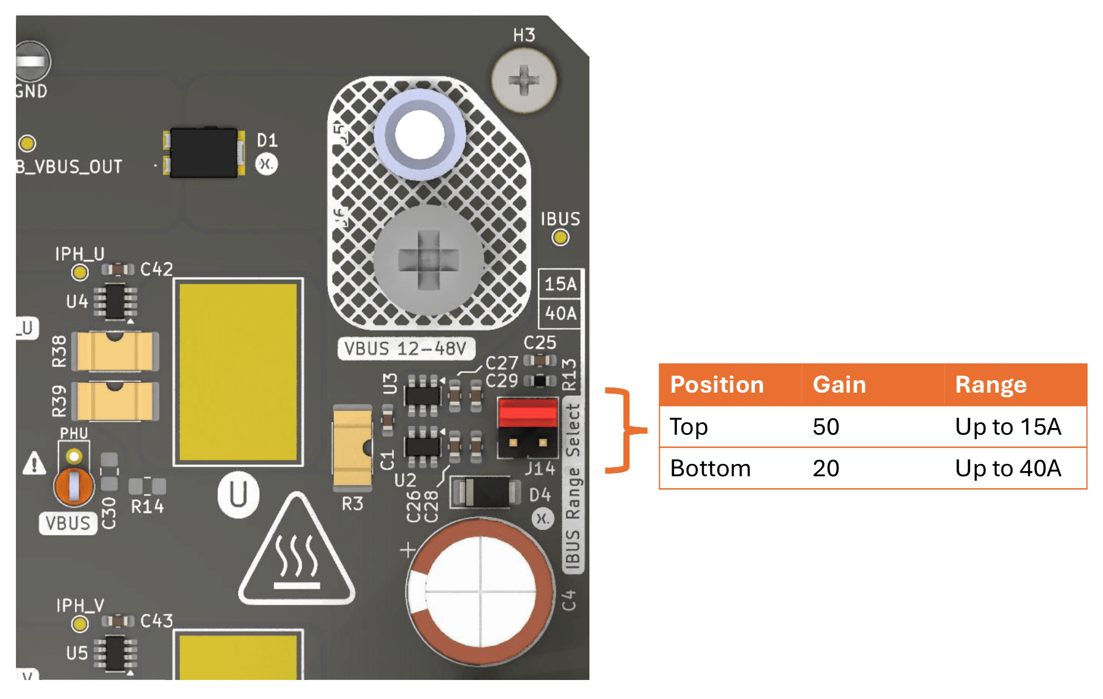
| #define IBUS_GAIN 50 |
Hi-side Current (IBUS) Gain for Current Measurement.
This macro defines the gain factor used in the current measurement circuit. The gain is a unit-less multiplier that amplifies the signal from the current sensor before it is read by the controller. It is used in the calculation to convert the sensor reading into an actual current value.
The NEVB-MTR1-I56-1 comes with two current op-amps with different gain factors:
| #define IBUS_SENSE_RESISTOR 4000 |
Hi-side Current (IBUS) Sense Resistor Value.
This macro specifies the resistance value of the current sense resistor in the system, measured in micro-ohms (μΩ). The value is used in conjunction with the current gain to calculate the actual current based on the voltage across the current sense resistor.
The NEVB-MTR1-I56-1 comes with a current sense resistor of value 4 mΩ. This is the default value.
| #define IBUS_WARNING_THRESHOLD 307 |
Hi-side Current (IBUS) Warning Threshold (Register Value)
This macro specifies the threshold value for current warning as a register value. When the current measured by the controller exceeds this threshold, it triggers the fault LED to be turned on.
The range is 0-1023.
This value is not scaled and represents the raw register value. To obtain the register value from the current in amperes, you can use the formula:
\[ \text{Register Value} = \frac{\text{CURRENT} \times \text{IBUS_SENSE_RESISTOR} \times \text{IBUS_GAIN}}{0.004888 \times 1000000} \]
Where:
The NEVB-MTR1-I56-1 comes with a default current gain factor of 50 and a current sense resistor of value 4 mΩ. This corresponds to approximately 0.0244 amperes (A) per register value. The default value is 307 which corresponds to approximately 7.5 A.
| #define IPHASE_GAIN 20 |
In-line Phase Current Gain for Current Measurement.
This macro defines the gain factor used in the current measurement circuit. The gain is a unit-less multiplier that amplifies the signal from the current sensor before it is read by the controller. It is used in the calculation to convert the sensor reading into an actual current value.
The NEVB-MTR1-I56-1 comes with a single gain factor option for the in-line phase current measurement circuit - 20.
| #define IPHASE_SENSE_RESISTOR 2500 |
Hi-side Current (IBUS) Sense Resistor Value.
This macro specifies the resistance value of the current sense resistor in the system, measured in micro-ohms (μΩ). The value is used in conjunction with the current gain to calculate the actual current based on the voltage across the current sense resistor.
The NEVB-MTR1-I56-1 comes with a in-line phase current sense resistors of value 2.5 mΩ. This is the default value.
| #define MOTOR_POLES 8 |
| #define PID_K_D 0 |
PID Controller Derivative Gain Constant (Only for Closed Loop)
This macro specifies the derivative gain constant for the PID controller. This parameter accepts signed integer values in the int16_t range.
| #define PID_K_D_ENABLE TRUE |
PID Controller Derivative Control Enable Flag (Only for Closed Loop)
Set this flag to TRUE or FALSE to enable or disable derivative control in the PID controller.
| #define PID_K_I 10 |
PID Controller Integral Gain Constant (Only for Closed Loop)
This macro specifies the integral gain constant for the PID controller. This parameter accepts signed integer values in the int16_t range.
| #define PID_K_P 100 |
PID Controller Proportional Gain Constant (Only for Closed Loop)
This macro specifies the proportional gain constant for the PID controller. This parameter accepts signed integer values in the int16_t range.
| #define REMOTE_DEBUG_MODE FALSE |
| #define SPEED_CONTROL_METHOD SPEED_CONTROL_OPEN_LOOP |
Speed Control Method.
Select the type of speed control by setting this macro to either SPEED_CONTROL_OPEN_LOOP or SPEED_CONTROL_CLOSED_LOOP.
| #define SPEED_CONTROLLER_MAX_DELTA 1 |
Speed Controller Maximum Delta (Applicable for Open Loop Control)
This macro specifies the maximum allowed change in speed reference by the speed controller after each iteration of the speed loop when using open-loop speed control. Adjust this value as needed. When a user changes the requested speed input, this parameter limits the maximum allowed change per SPEED_CONTROLLER_TIME_BASE.
| #define SPEED_CONTROLLER_MAX_SPEED 400 |
Speed Controller Maximum Speed.
This macro specifies the maximum speed, to be used as a setpoint when the maximum speed reference value is input to the speed controller. This "speed" is given as rate of change of the hall effect sensors in Hz.
This parameter is crucial for ensuring that the speed controller does not attempt to change the motor speed beyond a safe and controlled rate.
| #define SPEED_CONTROLLER_TIME_BASE 200 |
Speed Controller Time Base.
This macro specifies the number of ticks between each iteration of the speed loop. One 'tick' is one PWM period. Adjust this value to set the speed control loop time base. Range is 1-255.
| #define TIM3_FREQ 200UL |
Desired Electrical Rotational Frequency for "Emulated" Motor.
This macro specifies the desired electrical rotational frequency for the "emulated" motor. The valid range is from 5.08 Hz to 167.67 KHz.
| #define TURN_OFF_MODE TURN_OFF_MODE_RAMP |
Turn Off Mode.
Set this macro to either TURN_OFF_MODE_COAST or TURN_OFF_MODE_RAMP to specify the desired turn mode.
| #define VBUS_RBOTTOM 6200 |
Bottom resistor value in the VBUS voltage potential divider.
This macro defines the value of the bottom resistor (RBOTTOM) in the potential divider circuit used for measuring the VBUS voltage. It is specified in ohms (Ω).
The value of RBOTTOM is used to determine the scaling factor for the ADC conversion in the VBUS voltage measurement circuit.
NEVB-MTR1-C-1 has a resistor divider with RTOP of 100 kΩ and RBOTTOM of 6.2 kΩ.
| #define VBUS_RTOP 100000 |
Top resistor value in the VBUS voltage potential divider.
This macro defines the value of the top resistor (RTOP) in the potential divider circuit used for measuring the VBUS voltage. It is specified in ohms (Ω).
The value of RTOP is used to determine the scaling factor for the ADC conversion in the VBUS voltage measurement circuit.
NEVB-MTR1-C-1 has a resistor divider with RTOP of 100 kΩ and RBOTTOM of 6.2 kΩ.
| #define WAIT_FOR_BOARD TRUE |
Wait for inverter board connection before starting execution.
When set to TRUE the firmware will wait for the inverter board to be connected (detected via the IBUS measurement) before enabling motor functionality and proceeding with normal operation. This helps prevent accidental startup when the inverter is not present.
Set to FALSE to skip the check and start immediately.