|
Motor Evaluation Kit NEVC-MCTRL-100-t01-1.0.0
Firmware for NEVB-MCTRL-100-01 for trapezoidal control of BLDC motors using Hall-effect sensors
|
|
Motor Evaluation Kit NEVC-MCTRL-100-t01-1.0.0
Firmware for NEVB-MCTRL-100-01 for trapezoidal control of BLDC motors using Hall-effect sensors
|
This project includes an implementation of the Standard Commands for Programmable Instruments (SCPI) protocol. SCPI is a widely-accepted standard for syntax and commands, designed to provide a uniform method of controlling test and measurement devices. For a quick overview of SCPI, please refer to SCPI Quick Guide.
This allows remote operation of the motor via any programming language or software compatible with SCPI.
Please note the SCPI implementation in this project is intended primarily for evaluation purposes only.
While our SCPI implementation adheres to the core principles of the SCPI standard and relevant IEEE standards, it is important to note that it may not fully comply with the full required specification. The implementation focuses on the essential commands and functionalities necessary for evaluation. For detailed command information, see Command Sets.
The SCPI commands available in this project are designed to be intuitive and easy to use, adhering to the conventional SCPI syntax. Users familiar with SCPI will find the command structure familiar and straightforward. For those new to SCPI, ample documentation is provided to guide through the basic commands and their usage, as detailed in the Quick Guide and Command Sets pages.
The modular nature of our SCPI implementation allows for customization and expansion. Users with specific needs can extend or modify the existing command set. This flexibility is further detailed in the sections SCPI Quick Guide and Command Sets.
This guide provides a quick overview of SCPI and its usage.
SCPI commands typically follow a hierarchical structure resembling a file path, starting with a root and followed by nodes separated by colons or semicolons. For example: MEASure:VOLTage:DC?.
MEASure).MOTOr:SPEEd).There are two primary types of SCPI commands:
*IDN?).CONFigure:MOTOr:ENABle).?).;).From the command set documentation, you can deduce both the short and long forms of SCPI commands by examining the case used in the command syntax.
For instance, take the command CONFigure:MOTOr:ENABle. The way it's written provides clues:
CONFigure:MOTOr:ENABle. It is the complete, full-length command.CONFigure:MOTOr:ENABle, the short form would be CONF:MOT:ENAB.This approach to determining short and long forms applies to all SCPI commands. The long form is always the full command, while the short form uses the least number of initial capitalized letters. This feature of SCPI provides a balance between readability and ease of typing, especially for users who interact with the commands frequently.
These examples demonstrate that SCPI commands are not case-sensitive and can be abbreviated to the shortest unique string:
*IDN?CONFigure:MOTOr:DIREction FORWardMEASure:VOLTage:DC?CONFigure:MOTOr:ENABle ONconFigure:motOR:enabLE ONCONF:MOT:ENAB ONConf:Mot:Enab ONSCPI's flexibility with command syntax makes it user-friendly and adaptable to various styles of interaction.
SCPI commands are sent to the instrument via a communication interface, such as GPIB, USB, LAN, or RS-232.
In this case, we are using a serial communication (like RS-232) via USB, and certain settings need to be correctly configured:
115200 bits per second.LF) as the line ending character.8.None.1 stop bit.After configuring these settings, the instrument processes the SCPI command and returns a response, especially for queries. This ensures reliable communication between the controlling system and the instrument.
To start using SCPI:
SCPI provides a standardized and intuitive way to communicate with and control test and measurement equipment. Its uniform syntax across different devices simplifies the process of instrument automation and data acquisition.
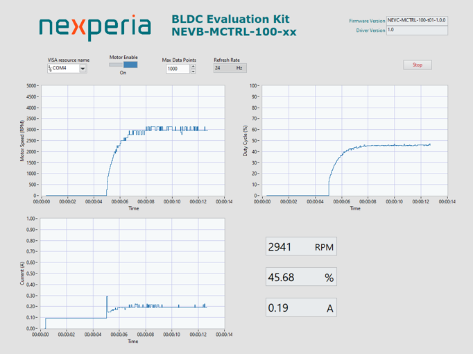
LabView is a popularly used in communicating with test and measurement equipment, and an example of LabView VI in the picture below shows the capabilities opportunities that the SCPI implementation can provide.
This page provides documentation for the SCPI (Standard Commands for Programmable Instruments) command sets implemented in this project. The commands are categorized based on their functions and compliance with SCPI and IEEE standards.
These commands are some of mandated by the SCPI standard (V1999.0 Section 4.1.1) that must be implemented in any SCPI-compliant device.
| Command | Description | Parameters | Return Value |
|---|---|---|---|
*CLS | Clears the event status register and error queue. | None. | None. |
*IDN? | Queries the identification string of the instrument. | None. | The identification string. |
*RST | Resets the instrument to its power-on state. | None. | None. |
These commands are some of the required commands as per SCPI standard (V1999.0 Section 4.2.1).
| Command | Description | Parameters | Return Value |
|---|---|---|---|
SYSTem:ERRor[:NEXT]? | Retrieves the next error from the error queue. | None. | The next error message or 0, "No error" if none. |
SYSTem:ERRor:COUNt? | Queries the count of errors in the error queue. | None. | The number of errors in the queue. |
Commands specific to motor control.
| Command | Description | Parameters | Return Value |
|---|---|---|---|
CONFigure:MOTOr:ENABle | Configures the motor enable state. | Boolean (ON or 1 to enable, OFF or 0 to disable). | None or error code and message if incorrect parameter. |
CONFigure:MOTOr:ENABle? | Queries the motor enable state. | None. | Boolean state of the motor (1 if enabled or 0 if disabled). |
CONFigure:MOTOr:GATE:FREQuency | Sets the gate drive frequency for the motor. | Frequency value in Hertz (Hz). Minimum 7183 Hz, maximum 100000 Hz. | None or error code and message if the frequency is out of range. |
CONFigure:MOTOr:GATE:FREQuency? | Queries the gate drive frequency. | None. | Current gate drive frequency in Hertz (Hz). |
CONFigure:MOTOr:GATE:DEADtime | Sets the gate dead time for the motor. | Dead time value in nanoseconds (ns). Min 350 ns, max 1750 ns. | None or error code and message if the dead time is out of range. |
CONFigure:MOTOr:GATE:DEADtime? | Queries the gate dead time. | None. | Current gate dead time in nanoseconds (ns). |
CONFigure:MOTOr:DIREction | Sets the motor direction. | Direction value (FORWard or REVErse). | None or error code and message if incorrect parameter. |
CONFigure:MOTOr:DIREction? | Queries the motor direction. | None. | The configured motor direction as a string (FORWard or REVErse). |
MEASure:MOTOr:SPEEd? | Measures the motor speed. | None. | Motor speed in revolutions per minute (RPM). |
MEASure:MOTOr:CURRent? | Measures the motor current. | None. | Motor current in Amperes (A). |
MEASure:MOTOr:DIREction? | Measures the motor direction. | None. | The motor direction as a string (FORWard, REVErse or UNKNown). |
MEASure:MOTOr:GATE:VOLTage? | Measures the gate voltage. | None. | Gate voltage in Volts (V). |
These commands are only available when SPEED_CONTROL_METHOD is SPEED_CONTROL_OPEN_LOOP.
| Command | Description | Parameters | Return Value |
|---|---|---|---|
CONFigure:MOTOr:GATE:DUTYcycle:SOURce | Sets the duty cycle source for the motor. | 0 for local (speed input pin) and 1 for remote. | None or error code and message if incorrect parameter. |
CONFigure:MOTOr:GATE:DUTYcycle | Sets the duty cycle for the motor. | Duty cycle in percentage (%). Minimum 0.0 %, maximum 100.0 % | None or error code and message if incorrect parameter. |
These commands are only available when SPEED_CONTROL_METHOD is SPEED_CONTROL_CLOSED_LOOP.
| Command | Description | Parameters | Return Value |
|---|---|---|---|
CONFigure:MOTOr:SPEEd:SOURce | Sets the speed source for the motor. | 0 for local (speed input pin) and 1 for remote. | None or error code and message if incorrect parameter. |
CONFigure:MOTOr:SPEEd | Sets the speed for the motor. | Speed in revolutions per minute (RPM). Minimum 0 RPM, maximum SPEED_CONTROLLER_MAX_SPEED | None or error code and message if incorrect parameter. |
This document provides a comprehensive overview of the SCPI command sets implemented in the project. It covers various categories including IEEE mandated commands, required SCPI commands, status subsystem commands, and motor control commands. For uncertain or future commands, placeholders are provided.
;).